
Unlike sources and power meters, which directly measure the loss of fiber optic cable plants, the work in OTDR is indirect. The source and meter duplicate the transmitter and receiver of the fiber optic transmission link, so measurements correlate well with actual system losses. In OTDR, however, the unique phenomenon of using fibers implies loss.
The biggest factor in fiber loss is scattering. It's like billiard balls bouncing off each other, but happens at the atomic level of photons (particles of light) and atoms or molecules. If you've ever noticed a flashlight shining through a beam of fog or smoky air, you look scattered. The color of scattered light is very sensitive, so as the wavelength of light becomes longer, toward the red end of the spectrum, the scattering becomes less. Actually very little, by a factor of the fourth power of the wavelength - which is the square of the square. Double the wavelength and you scatter it 16 times!
You can go outside on a sunny day and look up to the sensitivity of this wavelength. The sky is blue because sunlight filtered through the atmosphere scatters light like optical fiber. The sky takes on a hazy blue vibe due to more scattering of blue light.
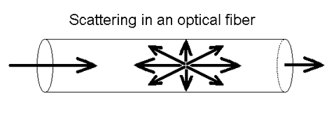
Figure 1 Scattering in the fiber
In optical fiber, the light is dispersed in all directions, as shown in Figure 1. OTDRs take advantage of this "backscattered light" so that their measurements include back to the source. It sends out a very high power pulse and measures the light back. At any point in time, the OTDR sees light scattered by the pulse in the region where the light passes through the fiber. Think of the OTDR pulse as a "virtual source", that is, all the fibers between the test itself and the OTDR, moving the fibers down. Since the velocity of the pulse can be calibrated as it passes along the fiber, the OTDR can correlate what it thinks is backscattered light with the actual position on the fiber. Thus it can create a display of the amount of backscattered light at any point in the fiber.
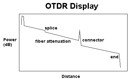
Figure 2 shows the OTDR
There are some calculations involved here. Remember that light is going out and coming back, so you have to factor that factor into the time calculation, halving the lost calculation time, because light looks at the loss in two ways. The power loss is a logarithmic function, so the power supply is measured in dB.
The amount of light scattered back to the OTDR is proportional to the scattering of the fiber, the peak power of the OTDR test pulse and the length of the pulse sent. If you need more scattered light to get a good measurement, you can increase the pulse peak power or pulse width as shown below.
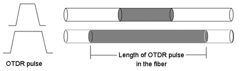
Figure 3 Increased pulse width increases backscatter level
Note that on the display shown in Figure 2, some events such as connectors show a large pulse in the backscatter trace above. i.e. reflections from the end of a connector, splice or fiber. They can be used to mark distances or even calculate the "back reflection" of a connector or splice, another parameter we wish to test in a single mode system.