

A Power Meter & Light Source is a low cost way to certify optical fiber. These two pieces of test equipment are used to measure fiber optic light continuity, loss and lastly, the actual strength of the optical signal.
Fiber Optic Signal Loss
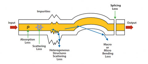
In fiber optics, when a beam of light which carries a signal goes through the optical fiber, the strength of that beam of light will diminish over distance. This means the signal strength becomes weaker. This loss of light power will affect the fiber optic network in a negative way. The loss of light power or attenuation of the optical fiber is caused by two issues, scattering and absorption of the light source. If the degradation is too great, then performance of the network will be affected.

The following can be the cause of sfiber optic signal los:
Tight Bends in the Cable
Dirty or Improperly Cleaned Connectors
Too much Stress on the Cable During Installation
Poorly Installed Connectors
Improper Splicing Technique
Poor Cable Quality
What Equipment is Needed to Conduct a Power Meter & Light Source Test?
Fiber Optic Cable to Test
Power Meter
Light Source
What Training Does an Installer Need to Use a Power Meter & Light Source?

A Power Meter and Light Source are a pretty simple piece of test equipment to use. An installer needs basic knowledge of cleaning fiber optic ends. The actual connection of the fiber to the test equipment is fairly straightforward. If you are familiar with handling fiber optics, the test is very easy. If you are new to fiber optics, this test should not present any issues. A simple short video explaining the test should be all you need.
Why use an OTDR in Place of a Power Meter & Light Source?
The Power Meter and Light Source are more limited than an OTDR. A Power Meter can only measure the received optical power. The OTDR can not only tell you if there is a break in the fiber, it can also measure the distance between the test point and the break. In addition, it is able to give you reflections for each connector. Even though the OTDR can reveal additional information, the Power Meter and Light Source are still an important piece of optical fiber test equipment and their importance should not be underestimated when testing an optical fiber network.
How Does A Power Meter & Light Source Work?
By attaching a reference cable to the light source, power can be measured at the opposite end of the fiber optic cable. The signal is sent from the light source down the fiber. These two pieces of test equipment are used to measure fiber optic light continuity, loss, and lastly, the actual quality of the signal. In short, it measures the power of the optical signal that has passed through the fiber cable from the light source.
Steps to Using a Power Meter and Light Source
Using the Power Meter & Light Source to test a fiber optic cable is relatively easy.
1.First, take the reference cord end face and clean it with 99% reagent grade isopropyl alcohol and lint-free fiber optic wipes.
2.Next, plug the reference cord into the light source and select the wavelength you are testing. When testing a multimode cord, attach a mandrel wrap to strip out the higher modes of light that can interfere with the test results. A mandrel wrap is not necessary for single mode.
3.Clean the other end of the reference cord and insert that end into the Power Meter. Now zero out the reference cord by hitting the "zero" button. After zeroing out, do not unplug the reference cord from the Light Source. Take the cord to be tested and clean one end, then attach the connector adapter. Clean the other end of the patch cord.
4.Remove the reference cord from the power meter and attach it to the test cord adapter. Insert the other end of the test cord into the power meter. The reading on the power meter will give you the loss on the connector mated to the reference cord only. To get the loss reading on the other end, simply unplug the test cord from the reference cord and switch the connectors. You have now completed the one cord reference test.
5.For a two cord reference test attach a connector adapter to the reference cord and insert the other end to the power meter. Zero out the power meter. You are now ready to get a loss reading for the entire cord being tested.
6.Take the test cord and clean both ends with the cleaning alcohol and wipes. Connect the test cord between the two reference cords. The power meter will show a full cord reading for total power loss. Record your loss as needed.